Feature
These features make the four-axis cam rotary table from Campower Precision Machinery a highly valuable machining equipment. It can meet the processing challenges of various complex workpieces while ensuring high efficiency, precision, and reliability. This is particularly crucial for industries that require high-quality machining, such as aerospace, automotive, and mold manufacturing.
High precision
The RDS cam rotary table complies with the ISO-230-2:2014 international standard for segmental positioning accuracy and repetitive positioning accuracy, ensuring a high level of machining precision. This is crucial for customers with demanding high-precision machining applications.
High speed
The high rotational speed enables the cam rotary table to achieve positioning and rotation quickly, thereby improving production efficiency.

"Cross roller"
bearing
Using cross roller bearing helps reduce internal structural wear, thereby extending the equipment's lifespan.
Suitable for vertical and horizontal mounting
This design enhances versatility, allowing the cam rotary table to be configured for vertical or horizontal operation based on specific requirements, which is particularly useful for different machining needs.
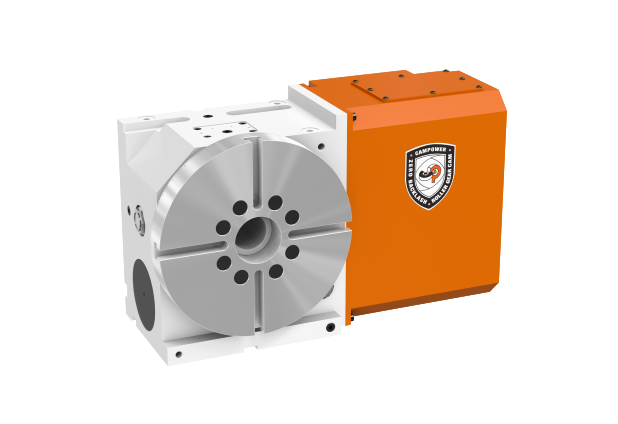
Newly optimized model
RDS series is a newly optimized four-axis cam rotary table that achieves high precision and efficiency based on an optimized structural design.

High CP
Drive mode
Unlike the commonly used worm and gear mechanisms in the market, Campower Precision Machinery employs roller cam mechanisms for both the fourth and fifth axes to drive the machine.
Roller cam mechanisms and worm and gear mechanisms are two different mechanical structures, and they differ in terms of stability, rigidity, and wear and tear:
|
|
Roller Cam Mechanism | Worm and Gear Mechanism |
| Stability | Exhibits higher stability. The design of roller cams allows for smoother motion, reducing vibration and instability. |
Lower stability, with potential for vibration and uncertainty, especially under high loads or high-speed conditions. |
|---|---|---|
| Rigidity | Possesses higher rigidity, providing better resistance to external forces and torque. | Relatively softer, potentially experiencing some deformation when subjected to external forces. |
| Wear and Tear | Lower wear and tear, capable of maintaining high precision over extended periods. | May experience wear and tear due to friction on contact surfaces, particularly during prolonged high-frequency use. |
| Backlash | Typically achieves zero backlash, offering more accurate motion control. | May have some backlash, affecting precision and the accuracy of motion. |
Applications
Specification
| Specification |
RDS200 |
RDS200H |
RDS250 |
RDS250L |
RDS300 |
|
|
|||
|---|---|---|---|---|---|---|---|---|---|---|
| Table Diameter | mm |
Ø200 |
Ø200 |
Ø250 | Ø250 | Ø300 | ||||
| Center Height(Vertical) | mm | 135 | 160 | 160 | 160 |
185 | ||||
| Table Surface Height(Horizontal) | mm | 195 | 195 |
205 |
205 | 215 | ||||
| Reference Hole Diameter | mm | Ø60H7 | Ø60H7 | Ø60H7 | Ø60H7 |
Ø90H7 |
||||
| Through Hole Diameter | mm | Ø45H7 | Ø45H7 | Ø45H7 | Ø45H7 | Ø60H7 | ||||
| Table Width | mm | 12H7 | 12H7 | 12H7 | 12H7 | 12H7 | ||||
| Degree of Reference Channel Width | mm |
14h7
|
18h7
|
18h7
|
18h7
|
18h7
|
||||
| MIN. Increment | deg. |
0.001° | 0.001 ° | 0.001 ° | 0.001 ° | 0.001 ° | ||||
| Max. Rotation Speed(Motor 3000 min-1) Values are Determined by the Servo Motor |
rpm | 83 | 83 | 50 | 50 | 50 | ||||
| Gear Ratio
|
1/36 | 1/36 | 1/60 | 1/60 | 1/60 | |||||
| Indexing Accuracy | arc-sec | 18 |
18 | 18 | 18 | 16 | ||||
| Repeatability Accuracy | arc-sec | 4 |
4 | 4 | 4 | 4 | ||||
| Servo Motor (Customer's choice) | FANUC |
αiF 4 βiS 8 |
αiF 4 βiS 8 |
αiF 4 βiS 8 |
αiF 4 βiS 8 |
αiF 8 βiS 12 |
||||
| MITSUBISHI | HG104S | HG104S | HG104S | HG104S | HG154S | |||||
| SIEMENS | 1FK7060 | 1FK7060 | 1FK7060 | 1FK7060 | 1FK7063 | |||||
| YASKAWA | SGM7G-09A | SGM7G-09A | SGM7G-09A |
SGM7G-09A
|
SGM7G-13A | |||||
| Clamp System (Pneumatic / Hydraulic) | P/H | P/H | H | H | H | |||||
| Pneumatic / Hydraulic Pressure |
Kg/cm²
|
5/35 | 5/35 | 35 | 35 | 35 | ||||
| Pneumatic / Hydraulic Clamping Torque |
Kg.m
|
13/40 |
13/40 | 60 | 60 | 90 | ||||
| MAX. Allowable Load on the Table | Vertical |

|
Kg | 90 |
90 | 130 | 130 | 160 | ||
| Vertical with Tailstock |

|
Kg | 180 | 180 | 260 | 260 | 320 | |||
| Horizontal |

|
Kg | 180 | 180 | 260 | 260 | 320 | |||
| MAX. Allowable Thrust Load on the Table (When clamped) | Allowable Axial Load |

|
Kgf | 1250 |
1250 | 2850 | 2850 | 3600 | ||
| MAX. Output Torque |

|
Kgf.m | 13/40 |
13/40 | 60 | 60 | 90 | |||
| Allowable Bending Torque |

|
Kgf.m | 45 |
45 | 135 | 135 | 150 | |||
| MAX. Allowable Moment of Inertia | Kgf.m² | 0.6 | 0.6 | 1.3 | 1.3 | 2 | ||||
| Net Weight(servo motor excluded) | Kg | 65 |
65 | 89 | 89 | 130 | ||||